 Difficulty:BeginnerTools Used:
3D Studio Max 2010
((Photoshop CS4)) [just for cropping images]
> you should have no problems using lower version releases of these programs

Hi party-people, this is zax and what you see here is an in-depth tutorial on basic modeling in Autodesk 3D Studio Max.
Some of you may already know this tutorial from the
MCA Community. In this thread im crafting an english remake to fix minor mistakes, pull together a better overview and reduce the amount text and pictures.
In the context of this tutorial you will learn how to model the Master Sword from the
The Legend of Zelda series using different modeling techniques in 3D Studio Max. In addition I will try to give you a feeling for the process of modeling and 3D modeling in general to give a view into what can be done and what has to be done.
Hope you guys enjoy it - I'd be happy to see any feedback you want to provide.

Ok guys, I rated this tutorials difficulty as
Beginner but make sure you have a clue what's up with some of those fancy buttons that welcome you warmly when starting up the software. I have not the space nor the time to go into detail about every function 3D Studio Max provides.
Knowing how to select polygons and move them around beforehand will save us time. Time we can spend on modeling techniques and art.
Well, let's start with some preliminary considerations. There are 3 important question you have to ask yourself before getting your hands dirty. The more detailed you can answer, the better your end result will be.
a) What am I going to create?Easy to answer, you may think, but just jumping into action like "Oh yea let's do a sword, mate!" is not enough. Think about the shape of your model and how you can work it out. An understanding of your model beforehand is important because it allows you to plan ahead. Predict edgeflow, size and count of polygons, shape division into several objects.
Get a plan where to start, where to go and what techniques to use.
b) What do I use the model for?The answer to this question leads to the restrictions applying to your model.
Eg. working on models for Warcraft 3, you don't want to go too deep into detail because the engine of this game won't handle too many polygons. Around 1000 per character is usual i guess. Working on WoW content is a different story. We can use up to 5-10k polygons on characters without encountering performance issues. Or are you going for the big deal? Talking about 3D animation for film and tv there may be no set limit.. atleast in performance. Rendertimes is another story
 c) Is there anything else to mind?
Keep everything in mind.
Look up what output file format you are going for. Make sure you use materials, textures and animation systems supported by your aimed engine. There may be restrictions in sidecount of polygons as well.
But most importantly: Be one step ahead of your work all the time. Don't forget the overall model while focussing on one detail.
One time it happened to me, that i spent 2 hrs on refining a body that would be covered under a cloak later on. You see what I mean? 
Now that our head is stuffed we can prepare for the modeling process. The most obvious way to help our imagination getting an idea of what the Master Sword will look like are reference images. Collecting images shouldn't be a porblem in the era of interwebs, google and co. However i decided to share the pics I used so you can follow this tutorial 1:1.
What images you use makes no difference as long as you get an idea of what you are going for.
[attachment=1:e6tfmq8f]refimg.rar[/attachment:e6tfmq8f]Finally everything is collected and it's time to run 3D Studio Max. One last advice before you start working on ANY project:
SAVE BACKUPS! SAVE SAVE SAVE! NEVER FORGET TO SAVE. YOU WANT TO SAVE EVERY NOW AND THEN. SOFTWARE IS NEVER 100% RELIABLE AND YOU WILL SHOOT A COW IF YOU LOSE AN HOUR OF WORK DUE TO A CRASH!
Personally, I prefer using the perspective viewport for most parts of the modeling. I just switch to the 2D-views from time to time to align vertices, edges and polygons properly and to place primitive objects on point. There is no formular on what viewport to use when. Everyone has to find his own style.
Enough talk for now, let's warm up:

If this is not your first time using 3D Studio Max you may know about the inbuilt function to set a bitmap up as viewport background. I dislike this methode because one wrong camera movement can misplace the whole setup troubling the user with additional refining on the scene. As often I have something up my sleeve to make things easier for you.
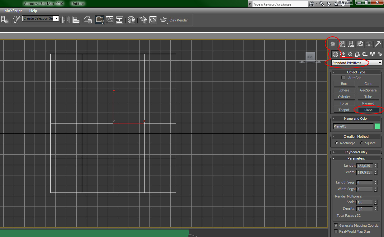
Look up the panel to the right. Open the index "Create" and choose "Geometry". The dropdown menu should show "Standard Primitives" as default. Click "Plane", activate Front viewport (click right mb) and drop a wonderful plane. This will be our canvas.
Now let's add some paint to the wall.
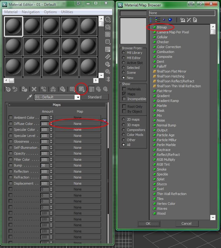
Open up the material editor (M), choose the first material (default), expand the categorie maps (you will probably have to scroll down the bottom part of the material editor to find it) and click on "None" next to "Diffuse Color". The new window popping up is called "Material/Map Browser". It contains many different maps for all the models you will create in your life.
For now the "Bitmap" is everything we need to assign a simple Diffuse Map, in other words a plain texture to our model.
Oh look, the software wants you to do more work. This is the major blue print for this project so you'll need a high resolution image with a one-side perspective. Good thing i added a fitting texture for the plane to the ref images you downloaded before. Pick mastersword2.bmp and click OK.
To finish the background setup drag and drop the material from the material editor over to your object and press the tiny button marked in the following screenshot:
Protip: Go to Customize/Preferences/Viewports/Configure Drive... and set Background and Download Texture Size to be highest resolution to improve quality of the textures rendered in viewport.
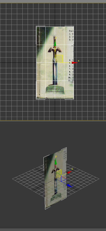
Use the Scale&Uniform and Move tools to give our background plane a proper resolution and place it at the center of the scene. If everything went well you should see something like this:
Rightclick the plane, enter Object Properties and tick on "Freeze", tick off "Show Frozen in Gray". Press OK.
Make sure everything is prepared according to your needs, the good stuff is going to start now.

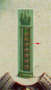
Activate the front viewport and create a box roughly covering the part of the hilt that goes into our heroes hand. Division into more segments is not needed, we will cover this later with a different technique. Open up the material editor, drag the second material over to the box, pick a color that makes you feel comfortable and lower it's opacity to about 30-40. Try around with the options until you are satisfyed. What we are trying to accomplish is a see-through effect so we can work on the model and see the blueprint at the same time.
That's what it looks like to me:
To get a better view into what just happened navigate around in the perspective viewport. You can also align the box a bit more using the Scale&Uniform Tool and Move tools. Im sure you want to adjust the thickness slightly. I did.
Now let's rightclick the new box, hover over "Convert to..." and convert it into an "Editable Poly". This allows us to finally edit the geometry of our object.
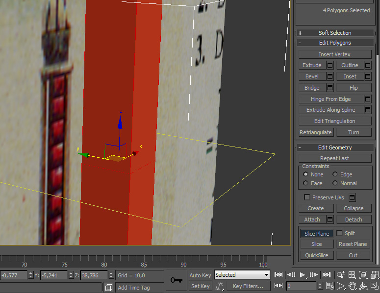
ATM the box does only consist of 6 polygons. To refine the geometry more are needed. Enter Polygon Selection Mode by clicking on the rectangle in the category "Selection" or just use the Shortcut "4". As you may have noticed, alot of new editing tools expanded on the right panel.
Select the polygon you want to divide (or just select all of them), scroll the panel down to "Edit Geometry" and click on "Slice Plane". An "empty" plane will appear. This is some kind of a helper object showing you where polygons will be divided, or sliced apart. Use your Move and Rotate tools to see how it works. A click on "Slice" (below the Slice Place button) will execute the Cut.
Let me introduce you to another technique to divide polygons into more polygons. Enter Edge Selection Mode (2) and select the 4 loooooong edges. Scroll the tool panel down to "Edit Edges" and click "Connect". This will connect all selected edges exactly at the center.
You can also free-hand cut into your model in Polygon Select Mode > Edit Geometry > Cut
Use the way that feels most straigh forward to you, that fits your working style or just let's you do this step the fastest to add some subdivisions to the box. Select the new created vertices (1) or edges (2) and scale them to get closer to the form of your sword on the blueprint.
Check our my subdivisions and scaling work:
Easy as eating cake, isn't it? If it does not work right away, take your time, delete and recreate the box and try again. Modeling has much to do with experience and it takes this time to collect this experience. Practice makes perfect.
Don't forget that you are working on a 3-dimensional object. We started our way in the 2D front viewport but we didn't stay there. Make sure everything looks fine in perspective.
When you are done lie back and take a nip of coffee out of your "IM THE BOSS KK" cup. Because you are the boss who is done with the first part of the master sword. If putting your feet up like the lazy bachelor I am is not what you intend until the model is refined to perfection feel free to invest some more time before continuing with step 4.3.

You learned techniques to create and edit/refine geometry? What else is there to know about modeling? To be honest, not much for the moment. You can do a lot with the stuff you just learned, the thing that takes time when learning 3D modeling is collecting experience and practicing the usage of the tools.
The crossguard is a good project to show what you have learned so far. It can be modeled with the techniques you learned but is not as easy shaped as the hilt. Use the reference images and your imagination to make it possible.
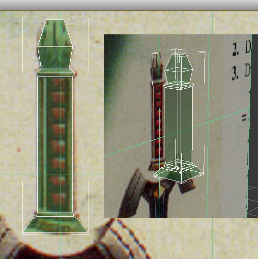
Start with creating a new box, covering the center of the crossguard and refine it until its shape recalls the master sword. See my work in progress to collect more impressions:
http://superparanoid.de/modcraftuts/3dtut/07_imp1.jpghttp://superparanoid.de/modcraftuts/3dtut/07_imp2.jpgLooking at the second picture you may think: "What nao, sir?". Like the total baller I am, I did some strange slices with the Edge-Connect technique. Im running into trouble at this point with the cross-guard all the time. Well, time to learn something new.
As you may have notices the two upper polygons have more than 4 sides. 5 to be exact. This is not what we want ever, because it looks better to render triangles and quads - game engines will only allow you to use triangles. So lets connect some vertices by selecting them in Vertex Mode (1) > Edit Vertices > Connect.
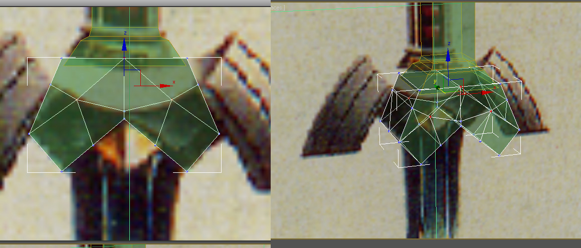
Much more like it, isn't it?
But the whole thing still looks a bit too blocky. Much like the box we created first. As we have in mind, the sides of the crossguard are blunt (kindy?
). Let's weld the top vertices to give our box the right shape.
Select the top vertices and use the Scale&Uniform tool to move them close to each other (see the picture below). Now use Edit Vertices > Weld to weld them together. Clicking on the small rectangle next to the "Weld" button unhides further options for this tool.
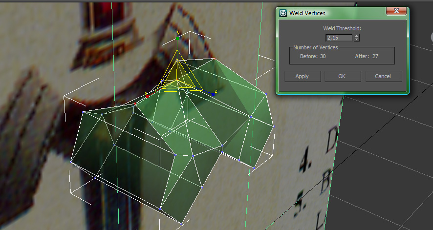
I repeated this step for 8 of the bottom vertices to resemble the bridge to the blade.
http://superparanoid.de/modcraftuts/3dtut/10_weld2.jpgI also decided to decrease the thickness of the crossguard for now because it looked kinda thick for me before. To do this, just leave any editing mode and use the Scale&Uniform tool.
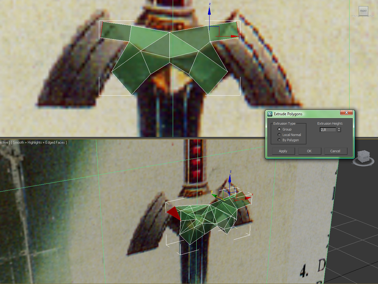
One last technique you will probably want to use for this piece is the extrusion of polygons. It allows you to extrude single or grouped polygons out of the object. We will do this to create these spikey extensions at the top (excuse my english on this part
). Select the upper polygon on both sides (polygon mode 4) and use Edit Polygons > Extrude to extrude them. I recommend using the advanced options, clicking the rectangle.
Yep, mate, not too shabby. Some more refining needed but we got what we intended.
http://superparanoid.de/modcraftuts/3dtut/12_ready.jpgWell, everything look set so far, time for the final extrusion. This part is tricky, cause parts of the geometry connect not too cooperative to the edge flow. Before extruding, delete the polygons i selected on the last pic so we can connect these parts to the new geometry later on.
http://superparanoid.de/modcraftuts/3dtut/13_step1.jpghttp://superparanoid.de/modcraftuts/3dtut/13_step2.jpgNow for the tricky part. We can't leave this hole open, indeed, but we also can't leave geometry overlapped as it would have happened. We need to connect the bottom vertice of the hole to the extrusion. I show you how to do it.
These steps have to be done on both sides (both extrusions).
First of all prepare some divisions on the extrusion to set up an edge flow for the geometry that is going to be connected/welded in. I selected the one of the new triangles created on the extrusion:
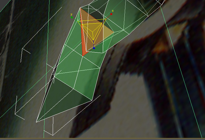
Delete the triangle to make a hole as counterpart to the first hole. Now you can move the bottom vertices of the first hole, close to the bottom vertices of the second hole to weld them together and finish this part of the geometry.
Congratulations, you solved a problem i had a lot of trouble with, when i worked on the old version of this tutorial. You are a true wanker.
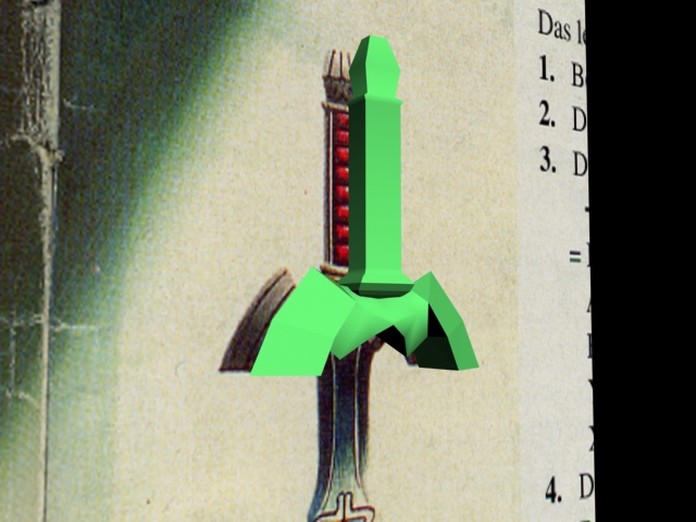
Let's take a quick render (F9) to see what is finished so far. I thickened the crossguard back to its old tickness because after the refining was done it looked better that way. Additionally it has to fit the hilt. You guys may notice that the hilt is now sticking out of the top part of the crossguard. No problem. We are free people, with endless imagination. Make it fit as you like.
My attempt:
Im fine with the hilt and crossguard so far. If I feel like changing or refining them later on i can return to this point at any time. And I'm sure I will. Viewing statistics (Shortcut 7) gives me a total polycount of 126 polys. That's pretty low and I still have a lot of space. Adding more polygons to make the geometry more fluid WILL HAPPEN!
I will add my finished and refined model at the end of this tutorial, for now let's stay with the basics.

Knowing how to slice, divide, extrude polygons, weld vertices and close holes you know everything you need to finish this final step. Mobilize your new gathered knowledge and experience about modeling techniques in 3D Studio Max to design the blade as it is burned into your brain for the last couple of hrs. I won't lead you as I did before but I will give you a suggestion on how I do it with some more work in progress shots.
Have fun.
http://superparanoid.de/modcraftuts/3dtut/15_blade1.jpghttp://superparanoid.de/modcraftuts/3dtut/15_blade2.jpghttp://superparanoid.de/modcraftuts/3dtut/15_blade3.jpghttp://superparanoid.de/modcraftuts/3dtut/15_blade4.jpgBaller.
To remove the unnatural shading from the objects select all polygons and look for the "Polygon: Smoothing Groups" category on the right panel. Make sure every number shows up (unclicked) telling you that no smoothing group is used. Don't mind the shading, the final shading comes along with the UVW Mapping I will probably introduce in another tutorial.

The basic modeling is done. Now it's your part refining the sword. I just reached 240 polygons. Remember the preliminary considerations when you thought about adding it to your WoW character? We can easily go for 500 polys for a weapon. At some detail but don't exaggerate.
When you are finally done, hide the plane, select every object (don't enter a selection mode) and go through the menu Group>Group to group every part of the sword together.
This is the final appearance of my THE LEGEND OF ZELDA MASTER SWORD!
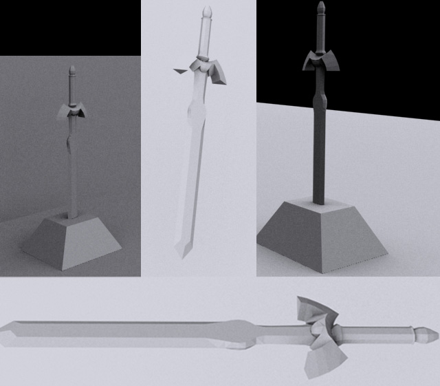

Your model is finished, congratulations, wanker.
But this is not the end of the way. You will want to unwrap it to add a texture, add animationsystems and finally export it to the engine you are creating it for. Check out the Modcraft forums for more tutorials and keep refining your modeling skills.
Modeling is more than just forming shapes. It's a learning process that never ends. Because every piece of experience you collect will improve the next model you create. This was just the first step.

[attachment=1:e6tfmq8f]refimg.rar[/attachment:e6tfmq8f]
[attachment=0:e6tfmq8f]05_blade_done.max[/attachment:e6tfmq8f]

